Diathermy Machines · Volume 5
Reading the Machine: Collecting Diathermy Apparatus
How to tell a 1920s spark-gap longwave set from a tube-driven shortwave cabinet, how to read the applicators and date the maker's plate, why the tungsten spark gaps outlive the machines that held them, and how to display a mains RF appliance safely.
Contents
5.1 About this volume
The four volumes before this one explained what a diathermy machine is — a device built to heat tissue through the skin with high-frequency current (Vol 1) — how it made that current as the field moved from spark gaps to vacuum tubes (Vol 2), what the heat does to tissue and the hazards that drove device safety (Vol 3), and how a genuine physiotherapy tool was oversold at mid-century (Vol 4). This closing volume is for the person who now owns one of these cabinets, or is about to: how to read it, how to date it, what the loose glass and metal parts in the case are, and — the load-bearing point, as with every mains-powered antique in this collection — why the sensible thing to do with a surviving unit is to display it cold, not to power it up.
Diathermy machines are less commonly collected than the violet-ray wands they are cousins to, and for a plain reason: they are bigger, heavier, and were institutional rather than domestic, so fewer survived and fewer are pretty. But the ones that do turn up — at medical-antique dealers, in physiotherapy-department clear-outs, and on the auction sites where Tesla-coil builders hunt for parts — are rewarding precisely because they are honest apparatus. This is a machine that really worked, and reading it is an exercise in engineering history, not in decoding a fraud.
5.2 Two eras on one shelf: spark-gap longwave vs. tube shortwave
The first and most useful thing a collector learns to do is sort a machine into one of two generations at a glance, because everything else — its date, its makers, its applicators, its value — follows from that split.
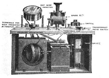
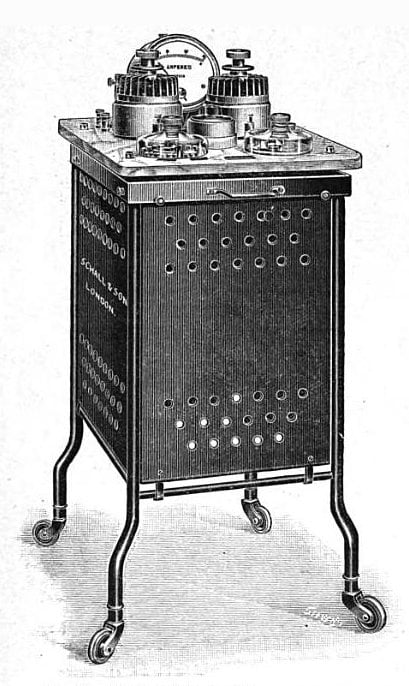
The first generation is the spark-gap longwave set of roughly the 1910s and 1920s. Inside it is a Tesla- or Oudin-type resonant coil driven by a spark gap, producing damped oscillations in the “longwave” band that later reference works fix at about 0.1–2 MHz. You can often hear this generation before you see it: a spark set is noisy in operation, a buzzing crackle that was one of the reasons the technology was eventually pushed off the air. On the bench these look like heavy electrical apparatus of the radio-pioneer era — an open or partly open chassis, a bank of spark gaps you can see, big output terminals, and a thermo-ammeter (a hot-wire meter that reads radio-frequency current directly) rather than the tidy tuning dial of later sets. The surviving H.G. Fischer Model G family is a good archetype: a portable metal-cornered cabinet, a carry handle, several stepped power settings, and its spark gaps mounted in a row.
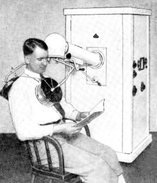
The second generation is the tube-driven shortwave cabinet of the later 1920s onward. Here the spark gap is gone, replaced by a vacuum-tube oscillator that pushed the working frequency up into the “shortwave” band — the range reference sources give as roughly 10–300 MHz, and which regulation eventually corralled onto the industrial-scientific-medical (ISM) channel of 27.12 MHz that most physiotherapy machines came to use. The face of a shortwave machine is the giveaway: a closed cabinet, a tuning dial you turned to resonate the output circuit to the patient, an output meter, and — instead of bare terminals for contact electrodes — insulated cables ending in flat plates or a hinged drum. This is the “physiotherapy department” look of the 1930s through the 1950s, and it is the pattern most surviving cased units belong to.
The dividing line is not perfectly clean — some large floor-standing machines (a Wappler is the name that recurs) combined spark and tube stages during the transition — but for a collector the rule holds: visible spark gaps and a hot-wire meter mean an early longwave set; a sealed cabinet with a tuning dial and plate-or-drum applicators mean a later shortwave one.
5.3 Reading the applicators: capacitive plate vs. inductive drum
If the cabinet dates the machine, the applicators tell you how it delivered its heat — and, usefully, they are the parts most likely to have survived loose in the case. Shortwave machines couple energy into the body in one of two ways, and the two look and behave quite differently.
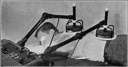
Capacitive (condenser) plates are the older idea: a pair of rigid metal plates or flexible pad electrodes, insulated from the skin, placed on opposite sides of the body part. The tissue between them becomes the dielectric of a capacitor, and the oscillating electric field heats it. In the case they present as two matched electrodes with their own cables — often felt or rubber pads, or glass-and-metal “space plates” on adjustable arms. Physically they concentrate their heating in the more resistive, lower-water, lower-conductivity tissue — skin and the fat layer — which is exactly the property that made them prone to superficial burns and which later machines tried to design around.
Inductive applicators are the alternative: a coil of cable, or that coil wound into a flat drum on a hinged arm, laid over a single site. The coil’s oscillating magnetic field induces eddy currents in the tissue, and because those currents flow best in conductive, electrolyte-rich tissue, an inductive drum heats muscle and deep soft tissue preferentially rather than the fat layer. A single drum applicator on an articulated arm — the “monode,” to use one of its several trade names — is the signature of the mature shortwave machine, and the reason a surviving cabinet with its drum intact is worth more than one with only bare terminals.
The practical collector’s summary: a matched pair of plates or pads = capacitive coupling; a single coil or drum = inductive coupling. Period practitioners chose between them by what they wanted to heat — plates for a superficial joint, a drum for a large muscle mass — and having both survive with a machine is a mark of completeness.
5.4 The tungsten spark gap: the part that outlives the machine
There is a quiet irony in collecting the earliest diathermy machines: the single most sought-after part is usually not the machine at all, but the spark gaps inside it — and the people who want them most are not medical-antique collectors but modern Tesla-coil builders, who prize a well-made antique gap as a component for their own high-voltage projects.
The reason is that a diathermy spark gap was a genuinely fine piece of engineering. A typical 1920s example is a tungsten-tipped centre electrode clad in a machined copper heat-sink fin — tungsten because it resists the erosion of a continuous spark, copper to carry the heat away — with the assembly nickel-plated and the electrodes mounted in pairs, one fixed and one adjustable through a fine thread turned by a Bakelite knob. Machines like the Fischer Model G carried several such gaps in series (three is a commonly reported count), so that a single working machine yields a small handful of these components. Collector listings put the tungsten tips at around a quarter-inch in diameter, though exact dimensions vary by maker and are best measured than assumed.
For the collector this has two consequences. First, it explains why so many early diathermy machines survive only as incomplete hulks: the spark gaps were harvested decades ago for the coil-building hobby, leaving the cabinet gutted. Second, it means a complete, un-robbed spark set — gaps present, adjuster knobs intact, meter unbroken — is a genuinely uncommon object and worth recording carefully before any thought of restoration. If you own one, the gaps are part of its history; a machine with its original gaps in place is a document, and one stripped for parts is a relic of somebody else’s hobby.
5.5 Identifying and dating a machine
Sort the generation first (above), then read the details, in roughly this order.
The maker’s plate and model. A moulded or riveted plate narrows both maker and era at a glance. The names that recur are H.G. Fischer (Chicago; early spark-gap Model G / portable Model GP sets), Liebel-Flarsheim (Cincinnati; later shortwave units such as the frequency-controlled SW-227 and the SW-660), McIntosh, Wappler, and, on the British side, Stanley Cox Ltd. of London, whose oak-cased shortwave sets are well represented in the Science Museum Group collection. Cross-check any model number against a maker catalogue or a museum object record rather than trusting a seller’s description — this field is full of machines mislabelled “quack device” by people who never learned that most diathermy was legitimate.
The electrical rating. A ratings plate or an old instruction sheet fixes the era’s mains world: a Fischer Model GP, for instance, was specified for 110 V, 60 Hz input at up to 500 W, with a stepped power control. A machine rated for direct-current mains, or carrying a very early two-pin fitting, sits at the older end.
The meter and the tuning. As above, a hot-wire thermo-ammeter (often dual-range, e.g. 0–1 A and 0–4 A) belongs to the spark generation; a tuning dial feeding a closed cabinet belongs to the tube shortwave generation. The presence of a resonance-tuning control is one of the surest signs you are holding a shortwave, not a longwave, machine.
The cabinet and cordage. Oak and mahogany cases, Bakelite knobs, cotton-braided (not PVC) cable, and cloth-covered mains flex all place a machine before roughly mid-century. Later hospital shortwave cabinets move to steel and crackle-finish enamel. None of these dates a machine to the year, but together they bracket it, and they should be cross-checked against the maker table a fuller treatment of the hardware (Vol 2) lays out.
5.6 Condition, safety, and display
This is the volume’s core message, and it is the same as for every mains device in this collection, stated flatly: a surviving diathermy machine is an unsafe antique mains appliance and a radio-frequency source, and the default sensible treatment is to display it, not to operate it. This volume therefore gives no operating instructions and no procedure for applying anything to a person. The reasons stack up.
- It is a high-voltage RF generator on perished insulation. Spark sets step mains up to kilovolt levels to drive the gaps; the century-old rubber-and-cloth cordage in these machines goes brittle and crumbles, early two-wire cords have no earth, and a fault can put mains potential where a hand does not expect it. Assume the wiring, the capacitors, and any wax-impregnated parts are degraded until proven otherwise — and proving otherwise is expert bench work, not a plug-it-in-and-see.
- The output was, by design, enough to burn. As Vol 3 sets out, diathermy deposits real heat deep in tissue; that is the whole point, and it is also why it was regulated. An uncontrolled antique in unknown condition has no place near skin.
- It radiates. Early spark diathermy was such a prolific source of radio interference that it helped drive the 1947 international allocation of the ISM bands (agreed at the Atlantic City conference of the International Telecommunication Union), the arrangement that later parked medical diathermy on 27.12 MHz. Running an unfiltered spark set today is not just unsafe, it is a broadband transmitter you are not licensed to operate.
- Possible asbestos and old fillings. As with the violet-ray sets, some period Bakelite and insulating board was asbestos-loaded; the correct posture is precautionary — do not sand, drill, cut, or abrade old mouldings, since intact material is low-risk and damage is what releases fibre.
Displayed cold, a diathermy machine is a superb object: the honest engineering cousin of the glowing quack apparatus around it. Lay a spark set open so its gaps and hot-wire meter show; stand a shortwave cabinet with its drum on its arm and a matched pair of plates beside it; keep the whole thing dry and out of direct sun to spare the coil, the iron, and any Bakelite. Provenance turns it from curiosity into document: a surviving instruction manual, a hospital or physiotherapy-department asset tag, a maker’s catalogue page, or a ratings plate ties the object to the exact clinical world Vol 1 describes. Photograph every applicator, record the maker’s plate and any model number, and — above all — count and photograph the spark gaps before anyone is tempted to harvest them. That record is the difference between “an old electrical thing” and a dated, attributed instrument of real medical history.
5.7 Where this volume hands off
This is the last volume of the Diathermy Machines dive. You now have the whole arc: what diathermy is and why it earns a clinical place (Vol 1); how it grew from spark-gap longwave to tube-driven shortwave and microwave (Vol 2); what its heat does to tissue and the hazards that built device safety (Vol 3); the honest clinical record set against mid-century overreach (Vol 4); and, here, how to read, date, and safely display the machine itself.
From here the collection branches back into the family diathermy came from. The spark coils that drove the earliest sets are the sober-medicine end of the story told in the High Frequency Currents dive, whose retail shadow is the Violet Ray Wands of the Quack wing — the same physics, the same coil, sold two entirely different ways. The low-frequency currents that do make nerves fire and muscles jump are the Faradic and Galvanic Machines dive; and the one place in this collection where high-frequency and low-frequency medical electricity part company most completely — the deliberate, consented induction of a seizure — is the Early Electroconvulsive Therapy dive. Each ends, as this one has, on the object a collector holds and how to read it.
Sources
- Diathermy — Wikipedia — the longwave (0.1–2 MHz spark/Tesla/Oudin, to the 1920s) vs. shortwave (10–300 MHz vacuum-tube, 1920s on) split; the ISM frequencies (13.56, 27.12, 40.68 MHz) and microwave bands (915 MHz, 2.45 GHz); capacitive-plate vs. inductive-coil coupling; and Nagelschmidt coining “diathermy” c. 1908 — used to anchor the two-generation identification scheme.
- 1920s H.G. Fischer Diathermy Unit — AM Innovations — a detailed teardown of a Fischer Model GP (portable Model G): 110 V / 60 Hz, up to 500 W, stepped power settings, dual-range thermo-ammeter (0–1 A / 0–4 A), metal-cornered portable cabinet, and three series spark gaps with tungsten-tipped centre electrodes clad in machined copper heat-sink fins with Bakelite gap adjusters — the primary source for the spark-set description and the tungsten-gap construction.
- Spark Gap Generator (Diathermy Replica) — AM Innovations — corroborates the tungsten-and-copper spark-gap construction, the fixed-plus-adjustable pairing, and the appeal of these finely made gaps to modern Tesla-coil builders.
- What are the differences between capacitive plates and inductive coils? — Balego — that capacitive plates use the body as a dielectric and heat higher-resistance/fatty superficial tissue, while an inductive coil/drum heats conductive muscle by induced currents; used for the “reading the applicators” section and the plate-vs-drum identification rule.
- Short wave diathermy — history.physio — the d’Arsonval/Oudin lineage, Nagelschmidt’s introduction of diathermy (given here as 1907), and period practice with “tea-plate sized” plate electrodes and “hose-pipe thick” induction cables — grounding the historical applicator description.
- ISM radio band — Wikipedia — the 1947 Atlantic City ITU conference that established the ISM bands, driven in part by FCC concern over diathermy interference, and the 27.12 MHz allocation — the basis for the radio-interference safety point.
- Vintage Liebel-Flarsheim Short-Wave Diathermy Machine, Model SW-660 (Worthpoint) and Liebel-Farsheim Short Wave Diathermy SW 227 — Jeff Behary / Internet Archive — surviving shortwave-machine models and maker (Liebel-Flarsheim, Cincinnati) used in the maker table.
- Diathermy set, United Kingdom, 1930 (co143473) and Short-wave diathermy apparatus (co137660) — Science Museum Group — museum specimens (oak-cased sets, Stanley Cox Ltd. shortwave units) grounding the cabinet/cordage dating cues and the figure plan.
- Diathermy Unit — Shortwave — Museum of Transport and Technology (MOTAT), New Zealand — a further museum object record of a cased shortwave unit, for the “physiotherapy department” display description.
Comments (0)