C. M. Sorensen Pressure and Suction · Volume 3
Inside the Machine
The eccentric pump, the flywheel and belt reduction, the universal motor, and the valves — what can be read from the outside of Machine No. 10010, and what is still waiting behind a cover plate.
Contents
3.1 About this volume
Vol 2 followed the air. This volume follows the metal — the mechanism that moves it.
A word about method first. I have not taken this machine apart, and this volume is written accordingly. Everything below is either (a) visible in the photographs and stated as such, (b) specified in Sorensen’s own catalogue, or (c) general to small reciprocating air pumps of the 1910s–20s and flagged as inference rather than observation. Where I do not know, I say so, and the What is still unknown section collects those items into a checklist for the day the covers come off.
That restraint is deliberate. The single fastest way to write something wrong about an antique machine is to assume that the general case applies to the specific object in front of you, and this collection has been caught by exactly that before. ⟨verify⟩ markers below indicate claims that need the machine opened, or a document found, before they should be repeated as fact.
3.2 The drive train, read from outside
The power path has four elements, and all four are visible without removing anything.
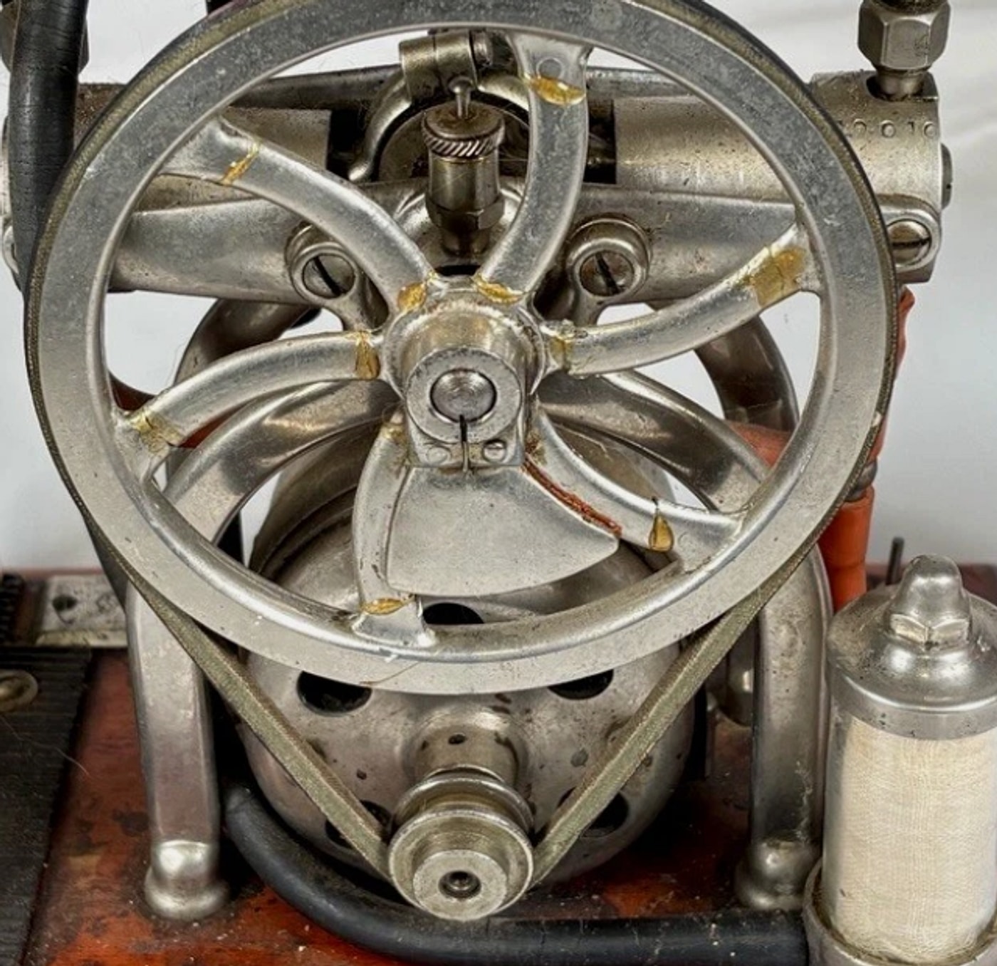
The motor is a small enclosed drum standing on the mahogany base, its face pierced by a ring of circular ventilation holes. Sorensen rates it at 1/20 horsepower — about 37 watts.
A stepped pulley sits on the motor shaft. This is worth pausing on, because a stepped pulley is not a decoration: it is a speed change. Two (or more) diameters machined into one pulley let the operator move the belt from one step to another and change the pump’s running speed — and therefore its delivery rate — without touching the motor. Whether Sorensen intended this as a user adjustment or as a factory-set option for different models is not something the catalogue addresses. ⟨verify⟩
A belt runs from that stepped pulley up to the flywheel. In the photographs it reads as a round or narrow flat belt of the kind used across small machinery of the period; leather is the overwhelmingly likely material, and the catalogue’s standard equipment list — which includes “cord with attachment plug, extra belt, oilcan and wrench” — confirms that belts were treated as a consumable the owner would replace. That every machine shipped with a spare belt tells you how often they broke.
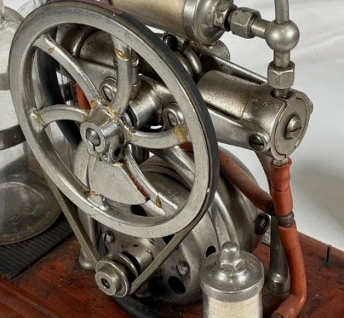
The flywheel is the largest single component: a substantial wheel with five curved, crescent-shaped spokes, mounted on the pump’s crankshaft with a split clamp and set screw at the hub. Because the motor pulley is small and the flywheel large, the belt is a speed reduction — the pump turns considerably slower than the motor. This is the correct arrangement: a universal motor is happiest at high speed, a reciprocating pump is not, and the belt reconciles them.
3.3 Why there is a flywheel at all
The flywheel is the most visually striking part of the machine and it is easy to read it as styling. It is not. It is solving a real problem, and the problem is specific to reciprocating machinery.
A piston pump does not absorb power evenly. Through the compression part of each stroke it demands a great deal of torque; through the return stroke it demands very little. Driven directly by a small motor, the result is a machine that surges and labours twice per revolution, delivers air in gulps, and stresses both belt and motor at the peaks. A 1/20 horsepower motor has no reserve to absorb that.
A flywheel fixes it by storing rotational energy. Its inertia carries the crank through the heavy part of the stroke using energy it accumulated during the light part, so the motor sees a roughly constant average load rather than a violently varying one. The output smooths out, the belt stops slipping, and a very small motor can drive a pump that would otherwise stall it.
The curved spokes are a genuine engineering feature rather than decoration, though the reason is not what people usually assume. Curved spokes were a standard foundry practice for cast wheels because a straight spoke, cooling and contracting between a hot rim and a hot hub, is put into tension and can crack the casting; a curved spoke can flex slightly and take up that contraction. Whether that logic applied to this particular wheel depends on whether it is a casting at all — it may be a fabricated or pressed part, which I cannot tell from photographs. ⟨verify⟩ As a secondary effect, spinning curved spokes move air, which does the pump’s crankcase no harm.
3.4 “Eccentric type” — what Sorensen meant
The catalogue is specific: “The pump is of the two-cylinder eccentric type.” That phrase carries real information.
In ordinary crank drive, the connecting rod runs to a crankpin — a journal offset from the shaft’s axis, carried between two webs. In eccentric drive, the shaft instead carries a circular disc mounted off-centre, and a strap encircles that disc and connects to the rod. As the shaft turns, the disc’s off-centre mounting pushes the strap back and forth exactly as a crank would, with a throw equal to twice the offset.
The mechanisms are kinematically identical; what differs is construction. An eccentric can be slid onto a plain, continuous shaft and clamped, requiring no forged or built-up crank web and letting the shaft run in simple bearings at both ends. For a small, cheap, robust pump this is an excellent choice, and it is the same reasoning that put eccentrics on steam-engine valve gear for a century.
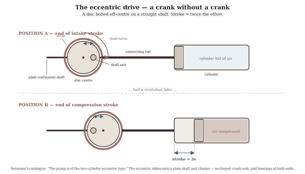
Whether both cylinders on this pump share one eccentric or run on two — and whether they are set opposed, at 180°, or in phase — is not visible from outside and matters for how smoothly the machine runs. ⟨verify⟩
3.5 The universal motor, and why the plate says A.C. & D.C.
The maker’s plate reads “VOLTS, CYCLES 110 A.C. & D.C.” That is not a hedge or a general-purpose marking. It is a precise technical statement, and the catalogue confirms what it means:
“All motors stated to be ‘universal’ operate on either direct or alternating current; and when ordering apparatus with universal motor, you need not mention the kind of current. But DO mention the VOLTAGE.”
A universal motor is a series-wound machine: the field windings are connected in series with the armature, and current reaches the armature through a commutator and carbon brushes. Because reversing the supply polarity reverses the current in both field and armature simultaneously, the torque direction is unchanged — so the motor runs on alternating current as happily as on direct.
That mattered enormously in the 1910s and 1920s, and it is one of the details that most firmly dates the machine’s world. American mains supply was not yet standardised. Substantial parts of New York City ran on direct current — Con Edison did not retire the last of its DC service until 2007 — and where alternating current had arrived, it was not reliably 60 hertz. A manufacturer selling a bench appliance nationally faced a genuine problem, and Sorensen’s answer is visible in its own price list: models with non-universal motors were sold as separate catalogue numbers, suffix “A” for direct current and “B” for 60-cycle alternating, and the customer had to specify. A universal motor made that whole question disappear.
The trade-off is brushes and a commutator, which wear, spark, and require maintenance — and which, as Vol 4 discusses, introduce an irony this machine cannot escape: an arcing motor in a room full of ether vapour is precisely the ignition source that the profession spent the following thirty years engineering out of operating theatres.
3.6 Valves, pistons, and a trap for the unwary
Nothing about the pump’s internal sealing and valving is visible from outside, and this section is therefore general-to-the-type rather than specific to Machine No. 10010. It is included because it contains one piece of knowledge that could save the machine from a well-meaning restorer.
Small air compressors of the 1910s–20s sealed their pistons in one of two ways: cast-iron piston rings, as in an engine, or leather cup packing — a leather cup, soaked in neatsfoot oil or tallow, whose flexible lip is pressed outward against the cylinder wall by the pressure it is containing. Both were common; which is fitted here is unknown. ⟨verify⟩
The trap concerns the leather cup, and it is worth stating explicitly:
In many period designs the leather cup is itself the intake valve, and it is deliberately loose on the piston. On the intake stroke the cup lags behind the piston, uncovering ports in the piston crown so air passes through into the cylinder. On the compression stroke it seats against the crown, closes those ports, and its lip is forced outward to seal the bore. A cup that moves on its piston is not worn out. It is working as designed.
Anyone who finds that looseness, diagnoses a failed part, and tightens it down has disabled the pump’s intake valve and will be baffled by a machine that no longer pumps.
The discharge side almost certainly uses either a thin steel reed (flapper) valve or a disc valve on a lapped seat, both standard for the era and both small enough to hide entirely within the head. ⟨verify⟩
3.7 The knurled control
On top of the pump head sits a knurled thumbscrew on a spring-loaded stem. It is the only operator adjustment on the machine apart from the switch and the belt position, and by elimination it must be the pressure control.
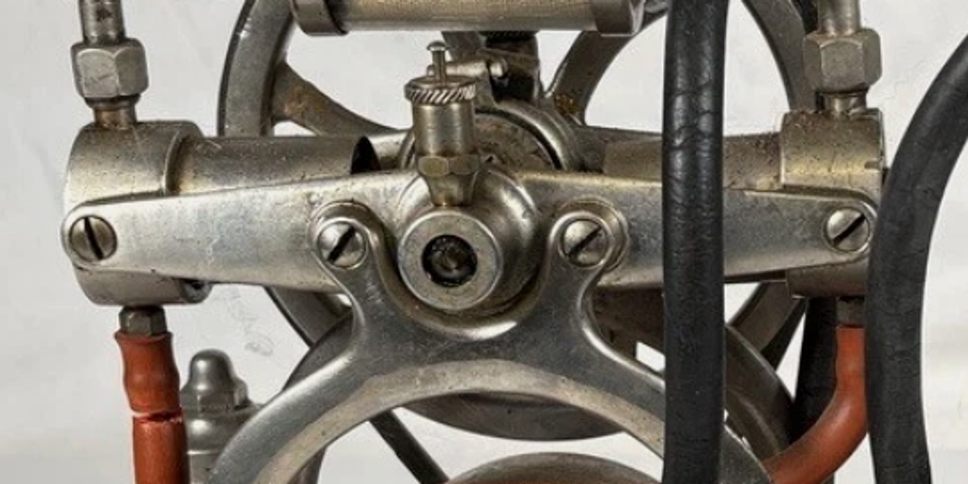
The mechanism is very likely a spring-loaded relief or bleed valve: the knurled screw sets the spring’s preload, the spring holds a poppet against a seat, and once pump pressure exceeds what the spring can hold, the valve lifts and vents the excess. Turn the screw down for more pressure, out for less. This is the simplest possible pressure regulator and it appears on countless small compressors.
There is, however, a documented reason not to assume it. Sorensen’s catalogue, describing the larger No. 460, mentions that machine’s control as “a new, improved type” which “diverts the air instead of holding it back against the pump.”
That is a real engineering distinction, and it tells us something about what came before. A control that “holds air back against the pump” is throttling the discharge — restricting the outlet so the pump works against a closed or partly closed path, which wastes power and heats a small motor. A control that “diverts” the air routes surplus flow away, so the pump always sees an easy path. The second is unambiguously better for a 1/20 horsepower machine.
The phrase “new, improved” implies the older arrangement was still in the catalogue when the newer one appeared. Which type sits on Machine No. 10010 is therefore a dating clue as well as a mechanical question — and one of the more useful ones available, given how little else about this machine can be dated (see Vol 6).
3.8 What is still unknown
Collected here, the open questions — the checklist for a teardown, roughly in order of how much each would settle.
- The cap-and-tube arrangement on the two bottles. Vol 2 flags an apparent inconsistency: a dip tube appears in the round jar, where the catalogue’s circuit puts it in the square ether bottle. Swapped caps, replacement glassware, or my misreading. This is the most consequential open item, because it governs whether the circuit diagram is right.
- The letters “N” and “M”. The 1917 advertisement says the outfit was switched between anaesthesia and office duty “by simply adjusting ‘N’ to ‘M’.” Two lettered positions on some valve or union. I have not located them, and finding them would confirm the machine is the same product the advertisement describes.
- The knurled control’s type — bleed/relief, or the later diverting kind. Dating evidence.
- The eccentric arrangement — one eccentric or two, and the phase relationship between cylinders.
- Piston sealing — rings or leather cups, and whether the cup carries intake ports.
- Valve type — reed or disc, and their condition.
- The stepped pulley — how many steps, and whether the belt position was meant to be changed in service.
- The flywheel’s construction — cast or fabricated.
- Any marks on the motor itself. Sorensen almost certainly bought motors in rather than winding their own; a supplier’s name would be a new thread entirely, and given the firm holds no patents at all (see Vol 6), the question of what Sorensen actually manufactured versus assembled is a live one.
- A Sorensen Service Parts List. The catalogue states: “We publish lists containing every part of every apparatus we manufacture… Please always mention Serial Number of Outfit.” Such a list would answer most of the above at a stroke. None has surfaced. It is the single most valuable document still missing.
Sources
- 1926 Catalog of Sorensen Tankless Apparatus (copyright 1925) — Internet Archive — “two-cylinder eccentric type” pump; the 1/20 hp universal motor; the universal-motor ordering note and the A/B suffixes for DC and 60-cycle AC models; standard equipment including cord, extra belt, oilcan and wrench; the No. 460’s “new, improved type” control that “diverts the air instead of holding it back against the pump”; and the Service Parts Lists note.
- The American Year-Book of Anesthesia and Analgesia, 1917–1918 — Internet Archive (Yale copy) — the “adjusting ‘N’ to ‘M’” reconfiguration between anaesthesia and office use.
- Universal motor — principle of series-wound AC/DC operation — why reversing supply polarity leaves torque direction unchanged.
- Con Edison’s last direct-current service, retired 2007 — the persistence of DC mains in New York City, and the commercial reason a universal motor was worth its brushes.
- Eccentric (mechanism) — construction and equivalence to a crank — the off-centre disc and strap, throw equal to twice the offset.
- Smokstak and Practical Machinist threads on 1920s reciprocating compressors — 1920s Wall/Quincy compressor, old air compressor valve arrangements, compressor identification — for period leather cup packing acting as its own intake valve, and for reed-versus-disc discharge valving. ⟨Collector-forum sources: reliable on the general type, not evidence about this specific machine.⟩
Comments (0)